FEM Studio
ElmerStudio — a modern desktop GUI for the Elmer FEM solver, born from research frustration and shared in case it's useful to anyone else.
ElmerStudio is a desktop interface for the Elmer FEM solver. It started as a personal project — I kept hitting the same friction every time I picked Elmer back up for research, and at some point I decided to fix it for myself. This is what came out. Sharing it here in case it saves you the same trips back to the docs.
Download
Free for personal, academic, and commercial use. Closed-source binary, no account required. See the license for the small print.
Ubuntu 24.04+ tested.
Windows 10 / 11.

Why this exists
I used Elmer for research and kept running into the same friction. Elmer's solver is genuinely excellent — decades of careful development by CSC and the Finnish FEM community, free, open source, and capable of holding its own against commercial codes. But every time I onboarded a student, the first hour with Elmer was spent on workflow rather than physics: setting up a problem meant editing the Solver Input File (.sif) by hand, mesh generation meant flipping between separate command-line tools, tweaking a parameter to study a trend meant duplicating the whole project, and viewing results meant launching ParaView, which itself has been broken on Ubuntu 24.04+ since early 2024 because of an upstream libexpat regression.
I built ElmerStudio first to remove those rough edges from my own workflow, then realised it might help students and newcomers get to the interesting parts of FEM faster. ElmerGUI, the official graphical frontend, remains a great option and a complementary tool — ElmerStudio simply takes a different approach in places where I wanted something different. Below is what's actually inside.
Start fast: pick a template, hit go
Open the app and you're already a click away from a working simulation. Four quick-start cards cover the most common Elmer workflows — Heat Conduction, Fluid Flow, Structural Mechanics, Electrostatics — each pre-wired to a sensible solver and starting material. A fifth card opens a four-step Custom Setup wizard that walks you through picking physics, simulation type and time-stepping, an existing mesh directory, and an initial material from the library. Either way, you end up with a complete SIF that you can run immediately and refine from there.
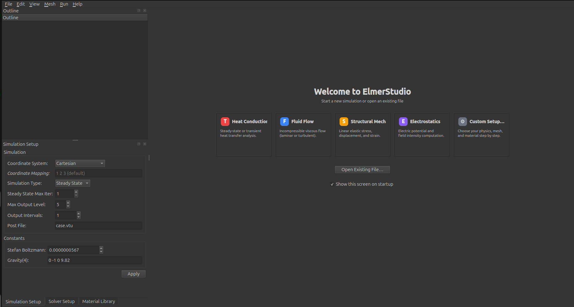
The welcome screen. Pick a template card or open an existing .sif file. Common simulation parameters sit in the dock on the left, ready to edit.
Built-in parametric mesh generator
Mesh creation is integrated. Eleven geometry templates (Segment 1D, Rectangle 2D, Rectangle with hole, L-shape, Two-material plate, Layered slab, Box 3D, axisymmetric cylinder, hollow cylinder, solid 3D cylinder, polar cylindrical shell) cover most academic and prototyping cases. Pick one, dial in the parameters, and a 3D preview updates as you type — no exporting to a separate mesh file format and re-importing.
The 2D paint canvas lets you assign material regions and boundary IDs visually before the mesh is ever generated. Five curated geometry-mapping modes — piecewise linear, circular arc, line-to-circle, line-to-sinusoid, and polygonal-angle — let you bend the otherwise-rectangular subcell boundaries into curves so the meshed result follows the actual shape of your domain.
Three dedicated wizards handle the structurally bigger operations: a Boundary Layer wizard for adding inflated boundary-aligned layers (typical for CFD wall treatment), an Extrusion wizard that lifts a 2D mesh into 3D as a stack of layers, and a Revolution wizard that sweeps a 2D section around an axis to produce an axisymmetric or full 3D solid. Each wizard ships with a live preview pane so you can sanity-check divisions and limits before committing.
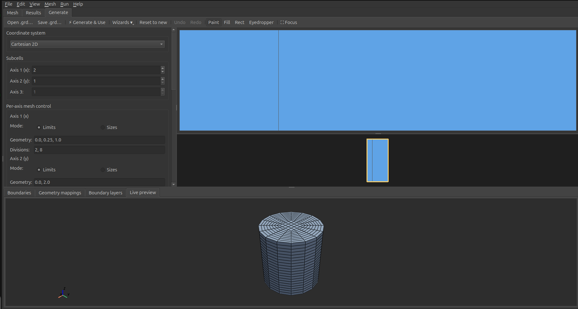
Four mesh-generator examples: rectangle with a hole, axisymmetric solid cylinder, hollow polar cylindrical shell, and a curved domain produced via geometry mappings. The 2D paint canvas, parametric controls, and live 3D preview update together as you edit.
Bring your own mesh, or clean up an existing one
External meshes import directly through File → Import Mesh…. Supported formats are Gmsh (.msh), Universal / Salome (.unv), ElmerGrid native (.grd), and ANSYS / Abaqus input decks (.ans, .inp). ElmerStudio shells out to ElmerGrid behind the scenes with the right format codes, so you don't have to look up -input 14 vs. -input 17 ever again. Existing Elmer mesh directories load by pointing at the folder.
Once a mesh is loaded, the Mesh menu exposes the operations you'd otherwise run by hand from the ElmerGrid command line:
- Mesh → Cleanup: Auto Clean, Merge Nodes, Remove Unused Nodes — the "fix actual mesh defects" operations. Each is a form-based dialog that runs ElmerGrid in place and reloads the result.
- Mesh → Transform: Scale, Translate, Rotate, Centralize.
- Mesh → Element Order: bump linear elements up to quadratic, or reduce a quadratic mesh back down.
- Mesh → Clone & Mirror: replicate a mesh in space or reflect it across an axis.
- Mesh → Refine Mesh: uniform refinement that splits each element (triangle → 4, tetrahedron → 8).
For inspecting what you've got, the same menu has Mesh Quality (toggles a colour overlay shading elements by quality metric so distorted regions jump out) and Mesh Statistics… (a popup with element counts, types, bounding box, and per-axis extents). Display options — boundary colouring by ID, wireframe, ground grid, origin axes, clip plane, slice plane — all live in the same menu and persist across runs.
Edit body and boundary IDs without re-meshing (new in 0.7+)
An import-time mesh almost never lands with the body and boundary IDs grouped the way your physics actually wants them. Three recurring challenges:
- "How do I group several boundary IDs under one Boundary Condition?" The classic workaround is the `Type` column in
mesh.boundary, but finding it from the GUI was historically opaque. - "My plate has a hole and the outer and inner perimeters got bundled under one BC index." ElmerGrid's side-code system is direction-aware but not topology-aware, so non-simply-connected domains lump topologically-disconnected boundaries together.
- "I have multiple physical volumes but Elmer sees one body." Cloning a mesh, mirroring it, or importing from a CAD tool that doesn't separate physical volumes at export all produce meshes where one ID covers multiple disconnected pieces.
The new Mesh → Bodies & Boundaries submenu collects fifteen operations that solve these directly, post-import, no re-meshing required. Four categories:
- Merge ranges of body or boundary IDs into one (Merge Body Range… / Merge Boundary Range…). Wraps the relevant ElmerGrid command-line flags but with a dialog that shows you the IDs and their element counts side-by- side, so you pick visually instead of trying to remember what's where. This is the direct fix for the "group several BCs under one Boundary Condition" question.
- Add a new boundary at the interface between two bodies (Add Interface Boundary…) or at the intersection of two existing boundaries (Add Intersection Boundary…). Useful for thermal contact, fluid-solid coupling, line loads, and edge constraints added without revisiting the mesher.
- Split a boundary four different ways. The headline is the one-click Split All Disconnected Boundaries — no dialog, no parameters: walks every boundary, finds the ones with more than one connected component, and splits each into fresh IDs. For the canonical plate-with-hole import, that's one click and the outer and inner perimeters become separate BCs. Per-boundary variants (Split Boundary by Components, by Feature Angle, by Plane, by Coordinate) handle more targeted cases — Feature Angle is the right tool for splitting a cube that imported with all six faces under one BC into per-face BCs (at the 30° default threshold, the cube's 90° corners register as feature edges and the six faces split cleanly).
- Split a body by connected components (Split Body by Components…), or extract a subset of bodies into a new self-contained mesh (Extract Bodies…). Split Body closes the "after Clone, everything is one body" gap directly. It offers face-adjacency (default — safer) or node-adjacency (more permissive — useful when touching-but-not-merged geometry should count as one body).
Every dialog shows a live ElmerGrid command preview at the bottom, so you see the exact invocation that's about to run before clicking OK — handy for learning the underlying ElmerGrid flags or scripting the same operation later. ID dropdowns are labelled with element counts ("3 (1,842 elements)") so you pick the right one visually instead of by memory. All operations write to a new output directory (suffixed with what was done, e.g. _split_disconnected) and leave the source mesh untouched.
The five splitting operations are implemented in pure Python, directly editing mesh.boundary / mesh.elements — ElmerGrid has no command for splitting one boundary into many, so these fill a real gap rather than wrap an existing flag. The body-component splitter and the topology-aware boundary splitter walk the element-adjacency graph properly, so they handle the pathological cases (a body that's "two cubes touching only at an edge", a boundary that's actually a Möbius strip) that simpler approaches would fail on.
Combine multiple meshes into one assembly (new in 0.7+)
Some problems need more than one mesh. A rotor next to a stator, a fuel rod inside a coolant channel, a pipe with an embedded sensor — each part probably came from a different source (one from your CAD export via Gmsh, another from an Elmer .grd script, a third from a Salome .unv), and historically the only way to join them was a multi-step ElmerGrid dance: write a glue file by hand, get the offset numbering right, hope the boundary IDs didn't collide, hope you remembered the mortar BC keywords correctly when you got to the SIF. I lost an afternoon to exactly this when a colleague asked for help with a rotor-stator coupling, and the result is the Assembly tab.
The workflow is now: add each source mesh as a Part, give it a position and orientation, preview the whole thing in 3D, and bake. Three bake modes cover the common cases:
- Concatenate — drop the parts side-by-side with offset IDs. Useful when the parts are spatially separate (e.g., two PCBs on a board) or when you want to author the inter-part interfaces yourself in the SIF.
- Weld — collapse coincident nodes across parts within a tolerance, so meshes that nominally touch but came from different sources become a single watertight mesh.
- Interface — keep both sides of every detected mating face distinct (each gets its own boundary ID) and emit a
mesh.mortarssidecar listing the pairs. This is the right mode for sliding contacts, non-conforming meshes, and rotor-stator setups.
Per-Part topology operations let you tidy each mesh before the bake without ever modifying the source files on disk: merge boundaries that the source mesher split unhelpfully, delete an interior interface that isn't really a boundary, extract only the bodies you want. Per-Part naming lets you label each body and boundary ID with something human-readable — rotor_slide, stator_outer, core — and those labels flow through to the baked mesh.names, the integrated Mesh tab's region selectors, and any SIF you write afterward.
For Interface-mode bakes, the Generate Mortar SIF… action turns the detected mortar pairs into ready-to-paste Boundary Condition blocks with proper Mortar BC = Integer N linkage, a projector kind auto-detected from the interface geometry (Rotational for cylindrical sliding boundaries, Radial for parallel periodic planes, Level Projector Generic as a universal fallback), and a Galerkin Projector = Logical True on every master block.
A Pick mode in the toolbar handles the flip side: when you've imported a mesh and don't know which numeric boundary tag corresponds to which physical face, switch Pick to Boundary, click a face in the 3D preview, and the status bar tells you the ID (and how many cells the group contains). The whole boundary group lights up translucent orange so you see what you've actually identified, not just one facet. Body picks work the same way. Once you know which IDs are which, label them in Edit Names and the rest of the workflow uses your labels.
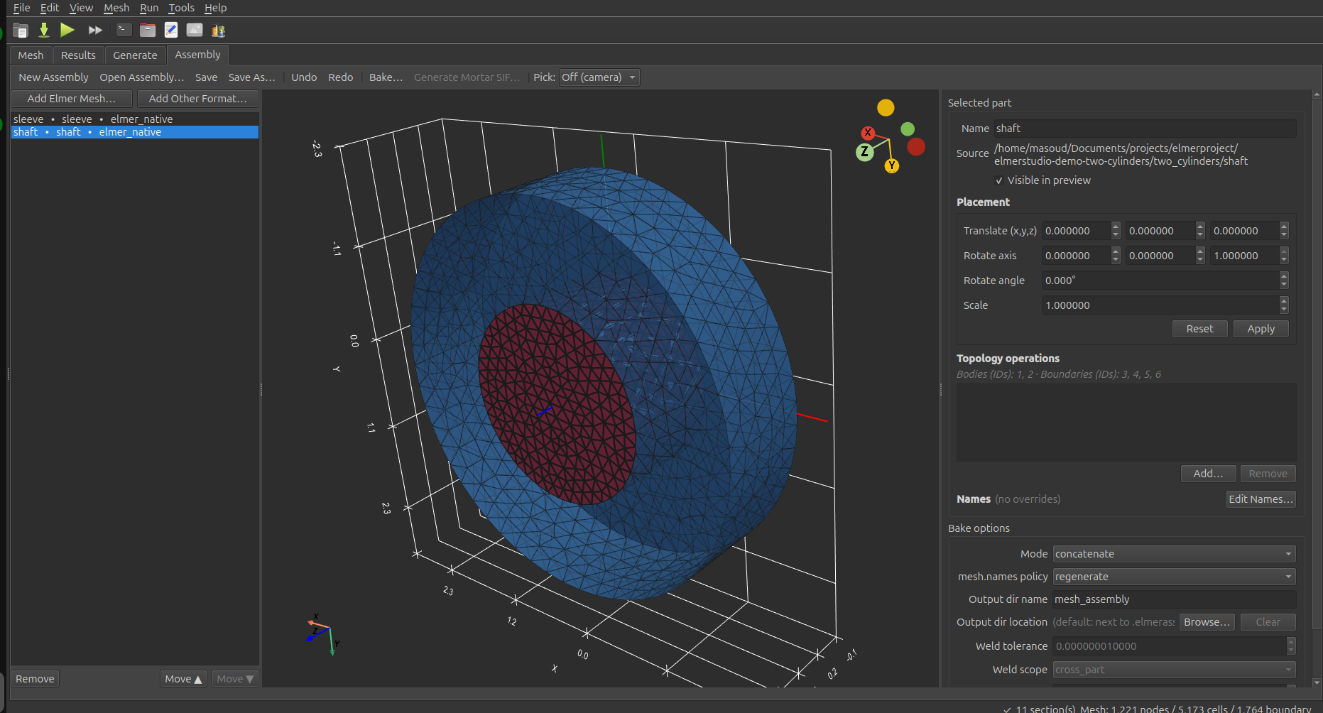
Two coaxial cylinders composed in the Assembly tab. The red inner shaft (two material subdomains — core and ring) is selected; the blue outer sleeve sits coaxially around it. Their mating surface at r=1 becomes a rotational mortar pair after an Interface-mode bake, and Generate Mortar SIF emits the matching Boundary Condition blocks.
One window, full workflow
The main editor is built around a single principle: everything you need to set up, run, and inspect a simulation lives in one window, not five. The semantic outline on the left groups the SIF into Setup (Header, Constants, Simulation), Physics (Solver, Equation), Domain (Body, Material, Body Force, Initial Condition, Component), and Boundaries (Boundary Condition). Click any entry to jump to it; right-click to delete, duplicate, or add a new section in place. Validation badges flag problems inline so issues find you, not the other way around.
The middle pane is a syntax-highlighted SIF editor with a line-number gutter, current-line highlight, monospace zoom (Ctrl + / Ctrl − / Ctrl 0), Find/Replace bar (Ctrl+F / Ctrl+H), and a comment-toggle shortcut (Ctrl + /). It round-trips losslessly with the form-based dock panels — edit either side and the other stays in sync. Dedicated docks handle the common authoring surfaces: a Simulation Setup dock for the Simulation and Constants sections, a Solver Setup dock that picks a solver from the bundled definitions and auto-renders its parameters as a form (with Equation, Solver, Body Force, and Initial Condition tabs), a Material Library dock with a category filter and a properties preview that injects materials with units handled, and a Boundary Conditions form for authoring BCs without touching the SIF.
SIF keyword autocomplete (new in 0.7+) — two characters into a keyword inside any known section (Solver, Material, Body Force, Boundary Condition, …) and a popup appears with the keywords valid for that section, ranked by exact-prefix match first then substring match. Tooltips show what each keyword does (the Whatis text from the bundled EDFs for EDF-sourced keywords, hand-written descriptions for the Header / Simulation / Constants / Body sections). Combo-valued keywords also complete to their allowed values once the user is past the = — type Convection = in a Solver block and the popup offers None / Constant / Computed. Top-level (between sections) the popup suggests section kinds. Esc dismisses; Enter / Tab accepts. Imported ElmerGUI EDF files contribute their keywords to the popup the same way the bundled ones do.
The right pane is an integrated VTU results viewer with field selection, eight built-in colormaps (viridis, plasma, coolwarm, RdYlBu, jet, turbo, inferno, magma), warp-by-vector with a scale factor, and a clip plane. For transient runs, a timestep slider beneath the viewport scrubs through the sequence while preserving your scalar selection. When you do need ParaView's full power, one click opens the current results in it. The "Open in ParaView" path also transparently re-encodes the VTU on the way out to dodge the libexpat 2.6.0–2.6.2 bug that breaks ParaView on Ubuntu 24.04+ — so it just works on a stock install with no patching.
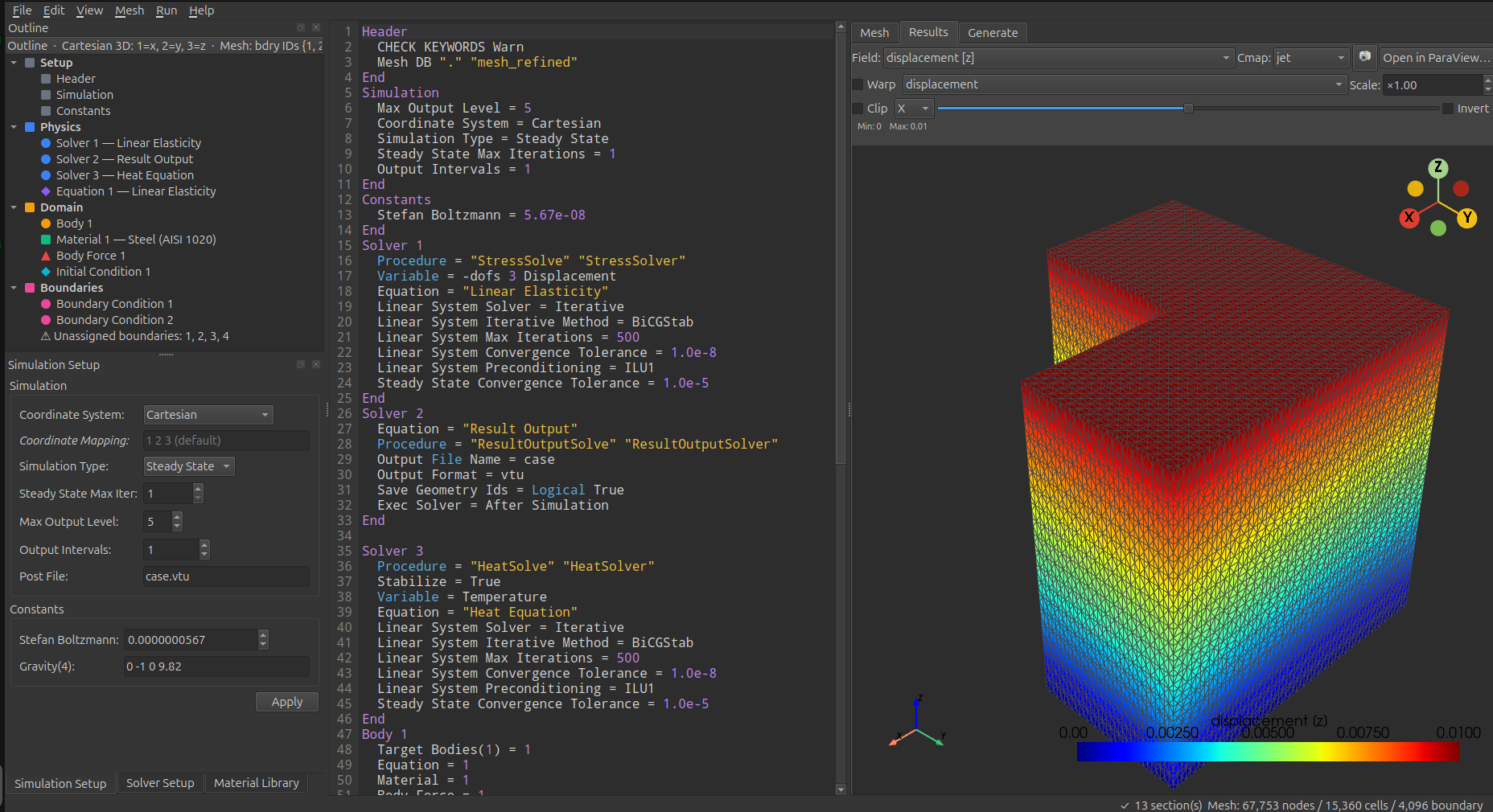
Outline tree, SIF editor, and integrated results viewer all in one window. This particular project couples linear elasticity with a heat equation; the right pane is showing the displacement field on a refined mesh of about 67k nodes and 15k cells.
Parameter sweeps as a first-class feature
Studying how a result depends on material properties, boundary conditions, or geometry is something Elmer users do constantly — and historically meant either duplicating the project N times or writing shell scripts that templated the SIF. ElmerStudio gives parameter sweeps a dedicated panel in the main window, no manual file editing required. Pick a keyword from any section in your SIF, declare the values you want to sweep over, and ElmerStudio handles the rest.
Two sweep modes ship out of the box. In Cartesian mode, ElmerStudio runs every combination of every parameter — full factorial, useful when you want to map the response surface across two or more independent dimensions. In Zipped mode, parameters advance together in lockstep, so you get N pre-paired configurations rather than N×M combinations — useful when you want to vary several keywords together along a curve in parameter space.
Each sweep step runs in its own subdirectory with its own generated SIF, runs the solver, and surfaces results in a live status table as the sweep progresses — values, exit code, wall time, and any error per step. You can abort the whole sweep, skip just the current step, or watch the convergence plot live for the active run. When the sweep finishes, the results viewer's slider scrubs through the output VTUs from each step while preserving your chosen scalar field, and a separate summary chart plots a chosen output metric (max / min / mean) against the swept parameter — line chart for one parameter, heatmap for two on a Cartesian grid. The structured directory tree of every run is also yours to post-process or feed into your own analysis script.
Other things you get
- Live convergence plotting while ElmerSolver runs. Per-solver residuals stream into a chart on a log y-axis in real time, so you see divergence the moment it happens instead of staring at terminal output.
- A 35-entry materials library — air, nitrogen, argon, water, common metals, polymers, and the usual suspects — searchable by category with units handled for you. One click injects the material properties into the active
Materialsection. - Pre-flight validation before each run. Verifies a mesh is loaded, at least one solver has a Procedure, every Equation has Active Solvers, every Boundary Condition has Target Boundaries assigned, and every Body references existing Material / Equation / Body Force / Initial Condition sections. Catches the Elmer gotcha where two Body sections claiming the same mesh ID silently honor only the first.
- Live solver output with a warning banner. ElmerSolver's stdout / stderr stream into a coloured pane as the run progresses. Lines matching known warning patterns are also collected separately and surfaced in a summary banner at the top, so warnings buried thousands of lines deep in the log don't go unseen.
- Eight bundled solver definitions covering common physics (heat equation, linear elasticity, Navier-Stokes, electrostatics, Helmholtz, advection-diffusion, static current, result output). Each renders as a structured form with the right keywords for that solver. Custom ElmerGUI-style EDF files import via File → Import Solver Definition….
- Parallel solver support through a settings dialog — pick the number of MPI processes and ElmerStudio invokes
ElmerSolver_mpiwith the right partitioning. Settings persist across sessions. - Cross-platform: same UI, same project files, same workflow on both Linux and Windows. Modern Qt 6 stack, no Qt 4 build battles on current distros.
- Self-contained binary. Linux AppImage and Windows installer ship with everything they need. No pip, no virtualenv, no PySide6 dependency hell.
What it isn't
- It isn't the solver. ElmerStudio is a frontend. You need ElmerSolver itself installed and on your PATH for simulations to run. Get it from elmerfem.org or your distribution's package manager.
- It isn't a CAD tool. The mesh generator covers parametric primitives well but doesn't do general CAD import. For complex geometries, mesh externally with Gmsh, Salome, or your CAD tool's mesh export, then load the resulting
.msh/.unv/.grd/.ans/.inpfile into ElmerStudio. - It isn't every Elmer feature. Elmer's solver has decades of accumulated capability. ElmerStudio ships eight solver definition files covering the most common physics; the rest is still accessible by editing the SIF directly in the integrated text view. If a feature you need would benefit from a structured form, file an issue.
- It isn't open source. Free as in beer, not as in speech. See the license for what's allowed and what isn't. This may change in the future.
Feedback & bug reports
The public release repository on GitHub doubles as the issue tracker: github.com/FEMStudio/femstudio-releases/issues. Bug reports, feature ideas, "this menu is confusing" observations, "what does this option mean" questions — all welcome. When reporting a bug, please include your OS, the ElmerStudio version (Help → About in the app, or run with --version), and what you were doing when it happened.
I read everything but reply on a rolling basis — this is a side effort, not a full-time gig.